Sunday, August 17, 2014

Phase Correlation

This is more of a grumble than an insight :)

I wanted to use "phase correlation" to do some optical flow, trying to smooth out some wretched noise in a film we had made. I had read about phase correlation a few times, and decided to give it a go.

The Wikipedia page http://en.wikipedia.org/wiki/Phase_correlation is great (as Wikipedia usually is.) In particular, it has good example pictures, and describes the math simply. Unfortunately, I believe that the math is unreadable. This is what it says:

Given two input images A and B

Apply a window function (e.g., a Hamming window) on both images to reduce edge effects. Then, calculate the discrete 2D Fourier transform of both images; FA and FB.

Calculate the cross-power spectrum by taking the complex conjugate of the second result, multiplying the Fourier transforms together elementwise, and normalizing this product elementwise.


     FA * FB*
R = ----------
     |FA FB*|

where FB* is the complex conjugate of FB and * is the Hadamard product of FA and FB*
What this means in code is this: [thank god for http://read.pudn.com/downloads163/sourcecode/windows/741399/Phase%20Correlation.doc ]

// do the hadamard product
float size;
for(i = 0; i < ras1->chan_size; i++) {
     img[i][0] = out1[i][0] * out2[i][0]
         + out1[i][1] * out2[i][1];
     img[i][1] = out1[i][1] * out2[i][0]
         - out1[i][0] * out2[i][1];
     size = sqrt(img[i][0]*img[i][0] + img[i][1]*img[i][1]);
     img[i][0] /= size;
     img[i][1] /= size;
}
Now, how are those related? The Hadamard product part I get, but How could I have known that I should divide each element of the product by the sqrt of the sum of the squares of each element?

My problem is that this is typical math shorthand, it really only makes sense if you already know the answer. A typical example is if you are trying to write sin(x) * sin(x) it is typically written sin^2(x) -- this is shorthand, and it makes for easier reading if you already know what it means, but it's just crazy. It's like the word ain't; it ain't a word.

I suppose code is the new math, and I should be happy that it exists.

Monday, January 19, 2009

score four

There is a classic game from my youth called score-four, it's one of the better three-dimensional tic-tac-toe games.  Unlike Qubic (I think that's what it was called) you can only play your marker on top of one that was already played.  You might think of it as a combination of Connect-4 and three-D tic-tac-toe.

I am always looking for new ways to engage the imagination of my boy with autism, and he was really interested in tic-tac-toe, so I thought I'd build a score four game, to see if he would be interested.  The problem with the real game is that it's pretty fragile, and I thought it wouldn't survive Thomas' attention for very long.

The time to write it, oddly, came as I was on a cruise over Christmas, 2008.  Everybody had gone to bed, and I spent a few hours writing the game in the ship's library.  I modeled it loosely on the game from "Funtastic".  I thought it was very important to make it simple to play, but also to allow the players to move around the game easily, to view all the possibilities.  So, I set it up so that if the player mouses down anywhere except near the top of one of the pegs, you can orbit the game -- but if you are near a peg, it locate-highlights, and clicking on it drops your marker on that peg.

Finally, in the last couple of days, I've added a computer opponent.  Sadly, even the stupidest computer opponent beats me almost every time -- I set it up to just try to get two-in-a-rows and three-in-a-rows, and to avoid me trying to do the same...that is enough.  The three-dimensional aspect of the game is challenging enough for me that I win rarely.

The other sad thing is that, so far, I've not had much luck interesting my little boy.  We'll see how that goes in the future -- I still have some tricks up my sleeve.

Anybody interested in a copy of the game, either as a Mac binary or OpenGL source, can write me.

Wednesday, February 13, 2008

X-Ray damage fix


An issue with shooting movies on film is that you don't see what you get until some time in the future. You have to take a lot of things on faith, that if all the machines work right, and the professionals working on the project do their jobs correctly, you will end up with the images you want on film when it gets back from the lab. A significant industry and methodology of working has been built up to make sure that this happens as well as it possibly can, and in large part it does the job. This is a real credit to people at Kodak, Arri, Panavision, the labs, and so on.

But sometimes things fail to work, and then it gets interesting.

I got a sequence of film recently that ended up having very bad X-Ray damage. It looked very much like this image from a Kodak publication I'm not using the images from the actual film for the obvious reasons.

Now, what you saw on this film was this blue band that moves from left to right periodically, this is how the X-rays expose this particular kind of film. The sinusoidal motion of the band is related to the way the film was exposed -- the X-rays slice through the wound roll of film in the can. A slice diagonally through a roll of film obviously makes a sinusoidal moving image.  [As an aside, it was clear that the period of the sine wave decreased over time, allowing us to determine that the X-ray damage happened before the film was exposed, rather than on the way back to the lab...]

If one could calculate the amount of damage at a particular point on the frame, then perhaps one could subtract that exposure and you would end up with a clean image. Now, it turns out that with this frame from Kodak, you could do this, as the sky is really absolutely black. If you assume that the beam doesn't change its character too much from the top to the bottom of the frame (this is empirically true) then you could just project the exposure generated from the top scanlines down to the bottom of the frame. You could even go further, and look at the top (black) part of the next frame, and make an X-ray exposure image that interpolates from the top of the frame to the bottom.

It turns out that this works pretty well. A significant issue, though, is that the X-ray damage is very noisy. When you try to subtract the blurry X-ray exposure interpolated image from the original damaged scan, you will find that many of the pixels would be less than zero. Clearly you would clip those to zero -- but then you wouldn't be subtracting enough exposure from that part of the film. The trick that works, then, is to diffuse that error (the amount that you couldn't subtract, because the value was less than zero) to neighboring brighter pixels.

I did this error propagation two ways. First, I took all the pixels that had remaining energy, and put them in a random order. Taking each pixel in turn, I would spiral away from that pixel looking for other pixels to subtract energy from.

The second way is that for every pixel with error, I divide the error by four, and add it to the adjacent pixels. This will slowly diffuse the error out. Doing this for multiple passes will allow us to finally find propagate all the error. It turns out that for large dark areas of the screen I needed many passes (on the order of 90) to get reasonable results. This is the technique I ended up using.

Great. Now you have something that works perfectly, as long as the top edge of your frame is black. It turns out that in reality (and in this particular movie I was working on) this is very seldom the case. Cinematographers want to take pictures of actual things, not black skies.

So...here's the tricky part. How can you find some black scanlines in your image. I urge you to think about this for a minute, because there are always some black scanlines, scanlines guaranteed to be only exposed by the X-ray, not by light. Where might one find these black scanlines?

Well, you say it that way and the question sort of answers itself. Film cameras expose frames one at a time, and film scanners scan those frames -- but there is almost always a black band between the frames! So, you just have to cajole your friendly film scanning service to load up the negative wrong, that is, so that rather than scanning frames, in the center of the scanned area you get the black band between the frames.

Anyway, our friendly neighborhood scanning service did this, (while rolling their eyes, wondering at the crazy things digital people ask them to do), and we got beautiful interstitial scans, analyzed them for the X-ray exposure, modeled the period, frequency, and phase of the sine wave to correctly smear the interstitial scanline across the frame, subtracted it out (in linear space, of course,) and it worked...pretty well. It got us about 95% of the way there.

A good friend of mine, Bill Taylor (ASC, and president of the Visual Effects Branch of the Academy) notes that this is one more example of the integrity of the analog, uncompressed, redundant nature of film. I think he has a very good point.

Saturday, January 12, 2008

More mac and linux -- parallelization

My company just bought a bunch of 8-core workstations -- it is high time to work on programs that take advantage of a modern computing environment.


I had written a renderer that used pthread and semaphores to partition and then manage the job, so I thought I'd see if I could do the same thing on my mac.  Unfortunately, I had used unnamed semaphores (sem_init(...)) on my Linux boxes, and the program failed (all threads appeared to be finished immediately) on the Leopard box.


Turns out that when you examine the error return, sem_init() has an entry point and prototype in the library and header file respectively, but it's actually "Not Implemented".  So, I switched over to named semaphores, and it all works perfectly.

In particular, on my 8-core box, I was getting some 6x speedup.


// start the threads
for(thread_id = 0; thread_id < n_proc; thread_id++) {
char sem_name[64];
printf("Starting thread %d\n", thread_id);
sprintf(sem_name, "sem_%d\n", thread_id);
if((semaphore[thread_id] = sem_open(sem_name, O_CREAT, 0777, 0)) == SEM_FAILED) {
printf("sem_open failed\n");
perror("sem_open error: ");
return -1;
}
ret = pthread_create(&thread[thread_id], NULL, (void *)median_scanlines, (void *)thread_id);
}

// wait for all threads to finish -- when thread is done, it calls sem_post(), then sem_wait below will unblock
for(thread_id = 0; thread_id < n_proc; thread_id++) {
printf("Waiting for thread %d to finish\n", thread_id);
sem_wait(semaphore[thread_id]);
}


Wednesday, January 09, 2008

just a little terminal icon


I hated the busy, but still low contrast, icon that comes with the very nice iTerm program I use on my MacBook Pro, so I found one on the 'net from an fphilipe, and made a tiff file that had alpha, to use as the icon, and it looks a lot sweeter.  Here it is, as two jpeg files (as Blogger won't let me post a TIFF file)

Friday, November 30, 2007

Qt success!


Finished my mp_edit program.  Halariously, the final problem was rendering text.  I was using the Qt renderText method in the QGLWidget object.  I noticed that my text was just not working, but then, it sort of worked when I only specified an x and y coordinate and no z coordinate.  Which -- made some tiny amount of sense, maybe, if I had the clipping planes wrong or something like that.
But no -- read the following description:


void QGLWidget::renderText ( int x, int y, const QString & str, const QFont & font = QFont(), int listBase = 2000 )
Renders the string str into the GL context of this widget.
x and y are specified in window coordinates, with the origin in the upper left-hand corner of the window. If font is not specified, the currently set application font will be used to render the string. To change the color of the rendered text you can use the glColor() call (or the qglColor() convenience function), just before the renderText() call.


void QGLWidget::renderText ( double x, double y, double z, const QString & str, const QFont & font = QFont(), int listBase = 2000 )
This is an overloaded member function, provided for convenience.
x, y and z are specified in scene or object coordinates relative to the currently set projection and model matrices. This can be useful if you want to annotate models with text labels and have the labels move with the model as it is rotated etc.
Note that this function only works properly if GL_DEPTH_TEST is enabled, and you have a properly initialized depth buffer.

OK, now, silly my, I read that the second function was an overloaded version of the first one, and thought that they did sort of the same thing -- but note that they really don't at all.  The first one takes two integer arguments, and works in screen space, and the second one takes three floating point arguments, and works in 3d space, and requires that the GL_DEPTH_TEST flag to be enabled.  They're two methods that share a name, but they are so wildly different in usage that, to my C-influenced mind, should be different commands.  I am certain that this is standard C-double-cross idiom, but it's going to take me a while to get used to it.

OK, the window resizing doesn't work yet, but everything else is fine.

I resurrected my old gdiff program for my new Mac -- I'm sure there's something better out there but I couldn't find it quickly.  It was nice to see that it compiled and ran almost immediately -- it was the first OpenGL program I wrote not on an SGI back probably 8 or 9 years ago.  If you want a copy of it, drop me a line to thadbeier@gmail.com

Qt Progress

Well, of course the problem I was having with the events not working is that my meta-objects were out of date.  I don't mean this blog to become an anti-C++ rant, but it could happen.  Easily.


See, C++ (most people pronounce it incorrectly, it's "C Double-Cross") is an abortion of a language.  Mr Stroustrup crammed as much OO-ness into C as he could, and stopped only when it became unstable -- it's sort of the Peter Principle applied to computer languages.  In any case, there are significant things you'd like to be able to do in an object-oriented language that are unavailable in C++, and one of them is determining the type of an object.  So, people extend C++ in wacky ways, and the Qt people have decided to build a meta-object system that processes header files into short C++ programs that encode the type information.


Of course, what happened to me is that one of these "moc" files was out of date.  There were no obvious warnings except that the program was just unresponsive -- none of the events caused any response whatsoever.

Anyway, now things work better -- the only thing remaining for me to declare mp_edit finished is the text -- I get an error that says "QOpenGLPaintEngine: Failed to create fragment programs." whenever it tries to draw text.  I'm not sure what this means.  Still, the program is somewhat useful at this time.

Thursday, November 29, 2007

Qt experiences -- 11/29


Today I tried to get the mp_edit program working, and it now comes up, and displays a curve, which is great.  The interface panel works as expected.

Unfortunately, events in the OpenGL window don't work at all.  I get no mousePressEvent, mouseReleaseEvent, mouseMoveEvent, or keyPressEvent events.

As usual, it's very difficult to tell what is going on.  It just sits there laughing at me and not doing anything.

I tried setting the setFocusPolicy, but it didn't help.

I'll next go back and try to use the hellogl window instead of my editing window, see if that gets events, and then see what that does different from what I am doing.  

mood: frustrated

Wednesday, November 28, 2007

Qt on my mac

Well, as I've said (but nobody has gotten the joke) I've gone over to the white side, and got a MacBook Pro. I'm going to be trying to port all of my code over to the mac, using the Qt library as the UI toolkit instead of my own Hui (Hammerhead UI) toolkit that I've been using for some 12 years now.

This means converting also to C++, and I suppose I have to just bite the bullet on this too.

I've ported a program over to Qt on Linux, and was trying to get it to work on my MacBook and had horrible problems.

I downloaded the Qt 4.3.2 source, configured and compiled it, and it just didn't work very well. Most of the OpenGL applications come up with a white featureless screen, as did the qtdemo application launcher. Basically, it looked hopeless -- and a plain white screen is pretty hard to debug.

However, downloading the binary .dmg version of Qt 4.3.2 things work better! Yeah!

My first program that I'll be porting is the mp_edit program, then I'll do my image viewer, and then my roto and tracking programs.

I've written a hui->qt convertor, and I'll be using that at least for the first pass of the ports.

I'm going to have to see how to draw text in the QGLWidget windows, but I don't expect that to be too challenging.

Wednesday, March 08, 2006

Soma


I have a boy with Autism, and I am always thinking about teaching tools for him. I have always liked the Soma puzzle by Piet Hein, and decided that that would be a nice puzzle to help exercize Thomas' 3D skills.

I built the puzzle out of wood, and tried it out, but it was just too hard for him. So, I painted the pieces red, yellow, and blue, and have made colored key images.

Because there are seven pieces and only three colors, it is still pretty darn challenging to build the models from the key images, but hopefully it will be possible. If not, I'll paint them seven different colors.

To make the key images, I wrote a program to solve the Soma models. [If Thomas does it that way, too, well, that'll be fine ;-) ] Then, I rendered them using my ambient occlusion texture mapping tool I've been developing for Fast and Furious 3: Tokyo Drift.

The solution program is pretty straightforward. It works by basically trying each block in each position in each orientation, then trying to put in the next block. This will work, but it's really slow. There are a maximum of 24 possible orientations of each block -- some will have fewer unique orientations due to the symmetry of the blocks -- and I'm just trying all 24 every time. Still, the longest solution times were less than a minute on my laptop, and usually less than a second.

A spectacular speedup could be obtained by ensuring that every six-connected region of the unfilled puzzle has a reasonable number of cells; either 3 or 4 modulo 4. I'm sure that if I tested for this after every piece was added, it would speed up the program to a few milliseconds. I've used a similar approach on the pentomino puzzle (A 2D puzzle with the 12 unique 5-piece pentominos filling a 6x10 rectangle, seared into my young brain by the description in Clarke's "Destination Earth". The puzzle-solving scene in that book probably had more to do with me wanting to program computers than anything else.)

The ambient occlusion calculation takes place in two steps. First, one makes an atlas of the different-colored parts of the model, laying out unique uv-coordinates for each polygon. I've written a very cool program to do automatic atlasing of models, and the uv layouts are often quite pretty. An example of an atlas-ed Mazda RX7 model is shown above. Basically the program works by finding all connected polygonal regions of a model that are relatively flat, projecting them onto the UV plane, and then packing those rectangular UV regions as tightly as possible. Doing this packing tightly will be a subject for a subsequent post.

Once the atlas is created, a ambient-occlusion texture map is created by scan-converting the uv-coordinates, and doing the ambient-occlusion ray-tracing at every pixel. Again, more detail later.


Tuesday, August 02, 2005

Kernel 2.6.12-1.1372_FC3smp and Nvidia

When upgrading my FC3 system to the 2.6.12-1.1372-FC3 kernel, I found that I could no longer build the Nvidia video drivers.

Of course, you have to install the kernel devel subsystem to make this work. For me, it was

kernel-smp-devel-2.6.12-1.1372_FC3.i686.rpm

Downloading this, and installing it, allowed the 7667 NVidia Linux driver to build and install fine. The 7667 driver seems to be a sweet spot in the NVidia driver evolution -- it seems to fix a number of problems in previous driver sets, at least on the mix of graphics cards we have at Hammerhead.

While on the subject of new kernels, I'm going to be (finally) installing new kernels on our renderfarm to take advantage of the ACPI capabilities. It turns out that the amount of power (and hence, cooling) used by render farms is a Really Big Deal. The new ACPI stuff in kernels 2.6.11 and up allow you to throttle the CPU when it isn't busy -- and our renderfarm typically sits idle at least 3/4 of the time. People at other facilities have noted a 50% power reduction on average once they began using this feature. This is great from any number of points of view.

Until I see something better, I'm going to go with the template provided by Alexander Beloin, available here:

http://www.wsu.edu/~ice124/throttle2.3b

Thursday, June 30, 2005

Fast ambient occlusion

Ambient occlusion, of course, is essential to modern 3D rendering. It adds "life" or "atmosphere" to 3D models in environments, and once you've seen anything with it, you'll never settle for anything less.

On The Chronicles of Riddick we did our first ambient occlusion rendering, and while it worked fine, it was very slow to compute. So slow, in fact, that we did ambient occlusion as a pre-process on the model, and saved the model with the occlusion baked in. Fortunately, we were dealing with almost-rigid spaceships and props most of the time, and this worked fine.

I noticed that all commercial renderers now support ambient occlusion to some extent. I've done some testing with the Gelato beta, and RenderMan 11.5 (both of course obsolete now.) We also did had an overly aggressive animator take home a shot and do the ambient occlusion on his home network using the Brazil renderer. My experience is that these obsolete versions of Gelato and RenderMan worked OK, but had significant artifacts and were pretty slow -- whereas the Brazil AO was amazingly fast and seemed artifact free, but it doesn't run on Linux (yet!) Brazil's AO seemed so fast that I could hardly believe it, they must be doing some amazing acceleration. I couldn't figure it out -- if you think about ambient occlusion, you realize that the close polygons are much more important than the far away ones -- the big ones are more important than the little ones -- and there has to be some way of coming up with an approximate solution quickly.

We also thought about using hardware rendering to accelerate ambient occlusion. We hired this spectacular programmer Hal Bertram to experiment with this, he did it in an afternoon by rendering the scene with the light in 256 different directions, and averaging these images together. Unfortunately, hardware (at the time, this was almost two years ago) was still pretty limited, and there were serious artifacts (aliasing, limited Z resolution, banding...) but it was super fast (a few seconds a frame.)

Finally I read of a nice acceleration for AO that is part of the GPU Gems book. As with many things in that book, it's a technique that applies perfectly well to traditional computers too -- although it would be slower on traditional computers (and perhaps that delta will increase over time as GPUs have been increasing in speed somewhat faster than CPUs) At this point, the article is available online at

http://download.nvidia.com/developer/GPU_Gems_2/GPU_Gems2_ch14.pdf

although you can always just go buy the book. The trick in this article is to represent each vertex as a disk, and calculate how much each disk shadows each other disk -- independently! -- and add them up. This is quick and easy, but it's still an O(n2) algorithm.

The acceleration comes from building a spatial tree. At each level of the tree, you have a list of disks in that part of the tree, plus some kind of approximation of all the disks from there on down. When calculating the occlusion for a particular vertex, you note how much shadow a particular subtree might contribute, and if it's less than a tolerance parameter, you use the approximate model.

The article in the book is just about that vague, leaving a lot of room for interpretation.

For my tree, I used a kd tree. The root of the tree contains the whole model, and the bounding box is divided into two subtrees by a median -- that is, half the discs are on one side of the plane, half on the other. I choose the axis of the plane (x, y, or z) to give the largest smallest extent. That is, if I have a box that has dimensions (10, 5, 3) and the median in each dimension is at (3, 2, 1) (say), then the x dimension would be partitioned into two parts 3 and 7 units wide, the y dimension into two parts 2 and 3 wide, and so on. The x dimension has the largest smaller half (3), so that cell is split in the x dimension. I think that probably any reasonable partition scheme would give almost identical results, but I thought that this scheme would yield somewhat-cubical boxes with equal numbers of discs reasonable quickly as you go down the tree.

At each level, I note the "large" discs, ones that cover a large part of the cell. As you traverse the tree, you have to evaluate the occlusion immediately for the large discs. These large discs are not included in the subtrees.

Finally, my approximation is that each node has an array of 24 structures. Imagine a cube, blow it up into a sphere, and imagine four equally-spaced normals emitted from each face. In each node in my kdtree, there are 24 entries containing the sum of the areas of the discs that correspond most closely to one of these normals, and the average position of the center of these discs.

At some point, when traversing the tree, you decide that you can use the approximate value, you build proxy discs from the array, and then you don't have to traverse the subtrees below that node. Here's my tree cell structure, just to help explain what's going on.


typedef struct KDtree {
BOX3F box; // bounding box of this cell
struct KDtree *child0; // child trees -- dividing plane immaterial
struct KDtree *child1;
int n_vert; // number of vertices at this level
OBJ_VERT **vert; // OBJ_VERT contains position, normal, area
float area[24]; // sum of areas of disks
V3F avg_pos[24]; // average position of disks with this normal
float total_area; // sum of area of all discs in subtree
} KDtree;

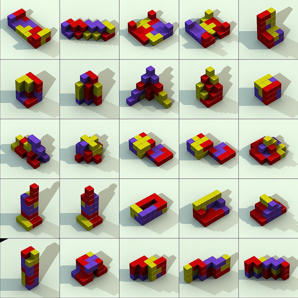
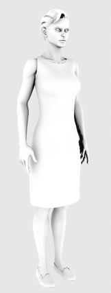
This all works great. On the 50,000 polygon model shown, I can calculate the ambient occlusion in less than 10 seconds with a simple 500 line program, with very good looking results. This compares to something like 10 minutes for my previous, heavily optimized, ray-tracing technique. Big win. If I spend some more time optimizing, I'll bet I can cut it down to 5 seconds.

jessica

One further note -- in the original GPU Gems 2 article, they recommend a very odd form factor calculation for the shadows

1 - (r * cos(thetae) * max(1, 4 * cos(thetar)) / sqrt(areae/pi + r2)

but later, when discussion radiance transfer, they use the more standard form. I use an equation similar to their radiance transfer equation

1 - (cos(thetae) * cos(thetar) * areae/(pi * r2))

I have to believe that the funky equation is designed to take into account some artifact of their approximation paradigm.

Tuesday, June 28, 2005

Hardware color correction update, continued


You have heard of the case of the dog that plays checkers? It's not that he doesn't play to well, it's amazing that he can do it at all? It's sort of like that sometimes with graphics programming.

I can't believe that my previous code worked at all, as I was not doing some very basic things. In particular, I was not using the texture handles correctly. Before any call to glTexParameteri, glTexImage2D, glTexImage3D, glTexSubImage2D and so on, you need to make sure that you're working with the correct texture unit, so you have to call glBindTexture(flag, handle) Doing this correctly gave the program a chance of working, and now I can reload the 3D color lookup table at will. I also had not called cgGLEnableTextureParameter() after calling cgGLSetTextureParameter(). Again, I can't imagine how the program worked at all before.

But anyway, now it all works. I had trouble when I enabled GL_DITHER, but that's a bit of an anachronism, anyway (back to the old SGI O2's, where double-buffered images were only 4-bits (dithered) per channel).

I had hoped to get some performance benefit by going to RGB instead of RGBA textures (less data to transfer, less data to lookup) but whatever gain there is miniscule at best. RGB textures require you to pad out each scanline to a 4-pixel boundary, which is kind of annoying (and not documented in the glTexture2D man page, but it is documented other places.) Similarly, I saw no speedup by using glTexSubImage2D instead of glTexImage2D to reload textures for each frame of a moving sequence -- at least on my development machine. I still use the glTexSubImage2D call whenever the image doesn't change size, because it seems like the right thing to do.

One minor annoyance is that it appears that there are limits to the size of texture images -- looking at 8k x 4k images, for example, doesn't seem to work -- where using glDrawPixels worked fine at that (and much larger) sizes. This is, so far, not much of a limitation -- but it could become one as the film industry moves to 4K images.

In the end, I'm getting the required 24 fps at 2048x1200 images with a 3D lookup table. Barely.

Friday, June 24, 2005

Hardware color correction update

I was somewhat devastated by the inability to re-write the 3D texture on the fly -- calling glTexImage3D again to replace the texture, in fact, caused a core dump. I can't believe that this is the spec, but I could be mistaken. In any case -- the solution is to call glTexSubImage3D to reload the texture data every frame. This seems to work perflectly.

Also, I should note for other people attempting to do that that in OpenGL if you want to use the vertex shaders, you can't create polygons the old IrisGL way -- you cannot use the glBegin(GL_POLYGON); glVertex3f(); glTexCoord2f(); ... glEnd(); sequence that all us old guys are familiar with. You have to use the glDrawArrays(GL_POLYGON, first, count); call. This means, as well, that you have to load up the arrays in a way that your vertex shader can get to them. These are done with the terribly intuitive1 calls (for a vertex position array called 'p' and texture coordinate array called 'uv')

cgGLSetParameterPointer(cgGetNamedParameter(vertexProgram, "Pobject"), 3, GL_FLOAT, 0, p);
cgGLSetParameterPointer(cgGetNamedParameter(vertexProgram, "TexUV"), 2, GL_FLOAT, 0, uv);

cgGLEnableClientState(cgGetNamedParameter(vertexProgram, "Pobject"));
cgGLEnableClientState(cgGetNamedParameter(vertexProgram, "TexUV"));


In any case, this ability to reload color correction tables is the second-to-last roadblock to releasing this image viewer. The last one is how to turn off the shaders to draw my annotations. This can't be too hard.


-------------------
1. HTML really needs a tag.

Thursday, June 23, 2005

Hardware color correction

I've heard about people using the fragment shaders in current NVIDIA graphics cards to do color correction, and I thought I'd give it a whirl. By "color correction" here I mean making things on our monitors look like the do on film. (For future historians, 'film' was an ancient analogue medium used to project images onto a screen.)

The first thing I tried was just to write a fragment shader that would intercept pixels from our normal image viewing application "ras_view". My first attempted fragment shader was as follows:

// convert from color to l gb r space and back

half4 main(float3 Color : COLOR) : COLOR
{
half l, gb, r, rad2;
half red, grn, blu;


l = dot(half3(0.33333, 0.33333, 0.33333), Color);
gb = dot(half3(0.00000, 0.70711, -0.70711), Color);
r = dot(half3(0.81650, -0.40825, -0.40825), Color);

gb = gb * gb;
r = r * r;

rad2 = 1 - (gb + r) * (1 - 2 * l) * 16;

return half4(Color * rad2, 1);
}


My observation about film is that the gray scale value track very nicely with the logarithmic curve specfied in the Kodak manual on the Cineon format. But, it turns out that as colors get more saturated, they get dramatically darker. The most striking example is the reproduction on film of pure blue. Loading (0,0,1) into a framebuffer makes a piercing blue, but on print film it ends up being almost completely black. My belief is that this is intentional, or at least the result of some intentional mucking with chemistry that Kodak has done to make filmed images look "better". Whatever. In any case, we have to match that.

So, in this first fragment shader, I transform the image by a matrix that converts RGB into a "gray", "red" and "green-blue" color. The RGB value of the image is scaled down by the the distance from the gray axis through the color cube.

This actually worked, after some typical cut-and-try hacking to get fragment shaders working under Linux (If you're easily frustrated, don't even go here. Probably doing this under Windows would be infinitely easier -- there are certainly many more examples to choose from. Not that I'd recommend using Windows for anything, of course.) Unfortunately, it was too slow. I was only getting some 12 frames/sec on 1000x500 pixel images. How terribly disappointing! The graphics card I was using, a (I know, I know, way too expensive) Quadro 3000, had some 16 pixel pipelines -- it should have been able to do this in a reasonable amount of time.

Insight was gained by using a null shader that just copied colors to the screen with no math at all. Just as slow. What can this mean?

Well, of course (you can all stop snickering now) the problem was that I was just using glDrawPixels to display my images. It turns out that if you avoid using fragment shaders you can get truly eye-watering glDrawPixels pixel transfers (on my box, now, I am getting 150M pixels/sec) But, sending them through any kind of fragment shader drops the speed to some 6M pixels/sec. A rather substantial difference.

Of course, the moral of the story is that these graphics cards are designed to draw texture mapped polygons (especially ones of splattering gore...) The right way to draw the image is to read the pictures, build a texture, load it, then render a polygon with that texture applied. Current graphics cards support TEXTURE_RECTANGLE, apparently exactly for this purpose. Rebuilding the program to work this way, and going through the shader pipeline, yielded a respectable 70M pixels/sec. One nice thing about using textures is that you can arbitrarily scale the image to do things like anamorphic projection and correction for non-square pixels (as on our plasma display, for example.)

Once I got to thinking about texture mapping, the obvious thing to do was to use 3D textures to specify the color transformation. This way you can get fairly arbitrary color transformations at respectable resolutions -- and the hardware does texture lookups incredibly quickly. Here are my current vertex and fragment shaders.


Vertex shader

void main(float4 Pobject : POSITION,
float2 TexUV : TEXCOORD0,
uniform float4x4 ModelViewProj,
out float4 HPosition : POSITION,
out float2 uv : TEXCOORD0)
{
HPosition = mul(ModelViewProj, Pobject);
uv = TexUV;
}


Fragment shader

half4 main(half2 uv : TEXCOORD0,
uniform samplerRECT image2d,
uniform sampler3D color3d) : COLOR
{
return half4(tex3D(color3d, texRECT(image2d, uv).xyz).xyz, 1); // With film-look 3d lut
}


If you're thinking of trying this, it seems that the expense of the shader is independent of its size (up to 64x64x64 textures), so you can really get very detailed color correction volumes in real-time. Pushing all the information through the OpenGL calls into the shaders is a mess, perhaps especially under Linux, but it does work in the end. I had serious problems reloading the 3D texture -- if I tried to call glTexImage3D more than once, the program core dumped. I'm sure that there's a good reason for this, but I don't know what it is. This means that, at the moment, I cannot change the lookup table once the application has started. This is more than a little annoying. I'm certain that I'm doing something wrong, but it's classic edit-compile-coredump debugging, without the core file saying anything useful. I also was unable to get the borders working in the 3D texture, but the CLAMP_TO_EDGE filtering did the job without the need for border pixels. It's conceivable that 3D textures just aren't all that robust yet.

In any case, I now have a proof-of-concept for this technique. It works, it provides general 3D color correction, it's fast. It's not released (even within Hammerhead) yet, but soon it will be.